How a Manual Gearbox Works Step by Step
Every time you dip the clutch and slot a gear, a precisely choreographed sequence of shafts, gears, and synchronisers happens inside the gearbox. Here’s exactly what occurs — from your foot on the pedal to the wheels turning at the right speed.
How a Manual Gearbox Works Step by Step
From clutch pedal to wheel — what actually happens inside a manual transmission when you change gear.
A manual gearbox works by using a driver-operated clutch to temporarily disconnect the engine from the drivetrain, allowing a set of rotating gear pairs on parallel shafts to be engaged or disengaged — changing the ratio at which engine speed is converted into wheel torque. That’s the one-sentence version. But what actually happens inside that metal housing bolted behind your engine is a surprisingly elegant piece of mechanical engineering, built around a handful of fundamental principles that haven’t changed much in over a century of motoring.
Whether you’re learning to drive a manual car for the first time, trying to understand why your gearbox crunches when you rush a change, or you’re curious about the engineering that still underpins most of the world’s motorsport — from Formula 1 to NASCAR to MotoGP — this guide covers the manual gearbox from first principles to the fine mechanical details.
A manual gearbox transmits engine power to the wheels through a series of interlocking gear pairs on two parallel shafts. The clutch disconnects the engine momentarily during shifts. A selector fork moves synchroniser rings to match shaft speeds before engagement, preventing grinding. Different gear pairs have different sizes — creating different ratios that trade speed for torque as road conditions demand.
Manual Gearbox Components: What’s Inside the Housing
Before we trace the flow of power from engine to wheel, it helps to know what you’re dealing with. A manual gearbox contains several key components, each with a specific job. Strip one apart on a workbench and it looks like an intimidating collection of shafts and gears — but the logic becomes clear quickly once you see how they relate to each other.
The Input Shaft
The input shaft (also called the first-motion shaft or primary shaft) connects directly to the engine via the clutch. When the clutch is engaged — meaning the pedal is up and the clutch plate is pressed against the flywheel — the input shaft spins at exactly the same speed as the engine’s crankshaft. When you press the clutch pedal, that connection is broken and the input shaft is free to slow down or stop independently of the engine.
The Countershaft (Layshaft)
The countershaft, sometimes called the layshaft, runs parallel to the input shaft. It’s permanently meshed with the input shaft through a constant-mesh gear pair — meaning it’s always turning whenever the input shaft is turning. The countershaft carries a series of different-sized gears, each one permanently attached to it. These are the gears that give the gearbox its different ratios.
The Output Shaft (Mainshaft)
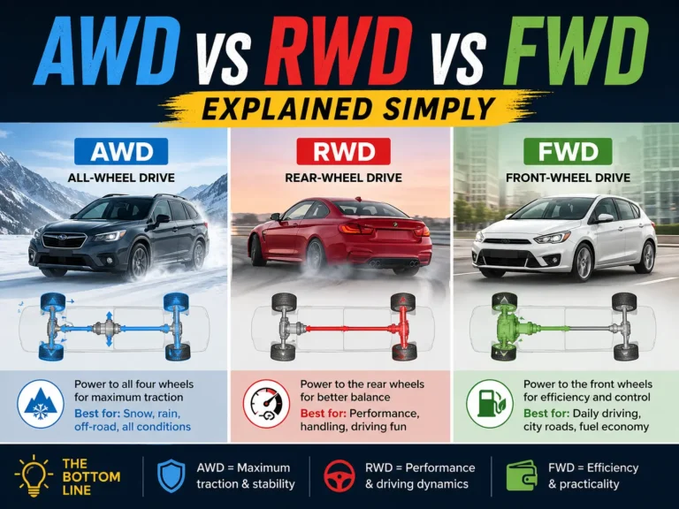
The output shaft (or mainshaft) is the shaft that exits the gearbox and drives the rest of the drivetrain — ultimately turning the wheels. In a rear-wheel-drive car, it connects to a propshaft; in a front-wheel-drive car, it connects directly to the differential. The output shaft carries the forward gear wheels too, but here’s the key difference: those gears can rotate freely on the output shaft — they spin around it without turning it — until a synchroniser locks one of them to the shaft.
The Gear Selector Forks
Gear selector forks are the mechanical link between the gear lever in your hand and the synchronisers inside the gearbox. Each fork sits in a groove on a synchroniser hub and slides it along the output shaft when you move the gear lever. Most gearboxes have three selector forks — one for 1st/2nd, one for 3rd/4th, and one for 5th/reverse. Only one fork can move at a time, which is why you have to go through neutral to change between, say, 2nd and 3rd.
The Synchronisers
Synchronisers (or synchromesh rings) are the unsung heroes of the modern gearbox. Their entire job is to match the rotational speed of the gear you’re selecting to the speed the output shaft is already spinning at, before locking them together. Without synchronisers, you’d have to rev-match every single gear change perfectly by ear — exactly what drivers do in old racing cars with “dog engagement” or “straight-cut” gearboxes. More on this later.

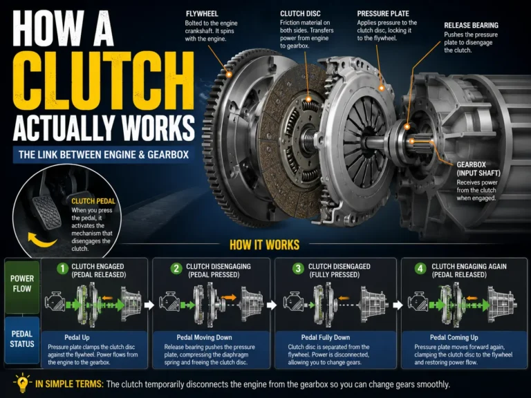
The Flywheel and Clutch Plate
Technically part of the clutch assembly rather than the gearbox itself, the flywheel bolts directly to the crankshaft and is the last rotating component on the engine side of the system. The clutch plate (friction disc) is clamped against it when the clutch is engaged. Understanding the flywheel matters because it stores rotational energy — and its weight affects how quickly engine speed changes when you dip the clutch. Performance cars often use lighter flywheels precisely to make the engine more responsive. Our guide on how car engines work covers the flywheel in more detail.
The Clutch: The On/Off Switch Between Engine and Gearbox
The clutch solves a fundamental problem: an internal combustion engine must keep running to stay alive, but the car needs to stop, start from rest, and change gears — all situations where you need to disconnect the engine from the drivetrain momentarily. The clutch is the mechanical switch that makes this possible.
Think of the clutch as a controlled slip device. When fully engaged, engine and gearbox spin as one. When fully released, they’re completely independent. The skill of driving a manual car lives in that zone between the two — where partial engagement allows smooth take-off from rest.
The Three Main Clutch Components
A standard single-plate dry clutch — the type used in the vast majority of road cars — consists of three main pieces working together:
Flywheel
Bolted to the crankshaft, this is the spinning surface on the engine side. It’s the thing the clutch plate presses against.
Clutch Plate (Friction Disc)
The disc sandwiched between the flywheel and pressure plate. It’s lined with friction material and splined to the input shaft, so when it’s clamped, the shaft turns with the engine.
Pressure Plate
A spring-loaded clamp that presses the friction disc against the flywheel. Push the pedal and a release bearing pushes on the pressure plate’s diaphragm spring, releasing the clamp.
What Happens When You Press the Clutch Pedal
Pressing the clutch pedal pulls or pushes a release bearing (also called a throw-out bearing) against the diaphragm spring at the centre of the pressure plate. This action pivots the spring fingers inward, which lifts the pressure plate away from the friction disc. The disc is now free — no longer clamped between flywheel and pressure plate — and the input shaft can slow down or stop independently of the engine, which keeps running normally.
Release the pedal and the diaphragm spring pushes the pressure plate back against the friction disc, clamping it firmly against the flywheel again. The engine and input shaft are once again locked together.
When you pull away from rest, the engine is spinning and the gearbox isn’t. You can’t snap from “completely disconnected” to “fully locked” in one instant — the jerk would stall the engine or snap the drivetrain. Instead, you bring the pedal up slowly through the “bite point,” where the friction disc slips slightly against the flywheel. This controlled slip gradually transfers drive to the wheels, letting both sides come to the same speed smoothly.

Manual Gearbox Operation: Step by Step
Here is exactly what happens — mechanically — every time you change gear in a manual car. We’ll walk through an upshift from 2nd to 3rd gear, since it’s the most common change and involves all the key events. The whole sequence happens in under a second.
In motorsport, the same mechanical events happen but the hardware changes dramatically. A GT3 race car uses a sequential gearbox where gears can only be selected one step at a time, and shifts take under 100 milliseconds. Formula 1 cars use semi-automatic paddle-shift systems with no clutch pedal for gear changes — hydraulic actuators do the clutch work in milliseconds, controlled by the driver’s fingers. The gear-engagement physics are identical; the speed and hardware are not.
Gear Ratios Explained: Why Different Gears Exist
A car engine produces useful power only within a specific rev range. Below it, there’s not enough torque to move the car. Above it, the engine runs out of breath. The problem is that a car needs to operate across a huge range of speeds — from stationary to motorway cruise — and the wheels need to spin across that entire range accordingly. Gear ratios solve this by multiplying or dividing the engine’s output to suit the conditions.
What a Gear Ratio Actually Means
A gear ratio is simply the number of times the input shaft rotates for every one rotation of the output shaft. A ratio of 3.5:1 means the input shaft (and engine) turns 3.5 times for every single turn of the output shaft. At that ratio, engine torque is multiplied 3.5 times at the wheels — but wheel speed is reduced by the same factor. This is 1st gear logic: enormous torque multiplication to move a heavy car from rest, at the cost of low vehicle speed per engine revolution.
A 1:1 ratio — which many gearboxes use for 4th gear — means the input and output shafts spin at identical speeds. No multiplication, no reduction. Direct drive. In 5th or 6th gear (overdrive), the ratio drops below 1:1, meaning the output shaft actually spins faster than the input shaft. The engine works at lower revs for a given road speed, which saves fuel and reduces wear.
| Gear | Typical Ratio | Effect on Torque | Effect on Speed | Primary Use |
|---|---|---|---|---|
| 1st | 3.5:1 – 4.0:1 | High multiplication (~3.5–4×) | Low wheel speed | Moving from rest, very slow crawl |
| 2nd | 2.0:1 – 2.5:1 | Moderate multiplication | Low-medium speed | Town driving, acceleration |
| 3rd | 1.4:1 – 1.7:1 | Light multiplication | Medium speed | General driving, overtaking |
| 4th | 1.0:1 – 1.2:1 | Near 1:1 (direct) | Medium-high speed | A-road cruise, 50–70 mph |
| 5th | 0.7:1 – 0.9:1 | Slight reduction (overdrive) | High wheel speed | Motorway/highway cruising |
| 6th | 0.6:1 – 0.8:1 | Overdrive | Highest wheel speed | Long-distance economy cruise |
These ratios are achieved purely through gear size. A small driving gear turning a large driven gear reduces speed and multiplies torque — like a bicycle in a low gear climbing a hill. A large driving gear turning a small driven gear does the opposite — high speed, less torque, like a bicycle sprinting on the flat. Every gear pair in the gearbox is a different combination of these sizes.
In racing, gear ratios are tailored precisely to each circuit. A short, twisty track with many slow corners needs closely stacked low ratios to maximise acceleration out of each bend. A high-speed oval needs tall, spread-out ratios to let the engine operate near peak power for as long as possible. Understanding torque and horsepower helps explain why these choices matter so much.

Synchromesh Gearbox: Why Modern Gearboxes Don’t Crunch
Before synchromesh gearboxes became widespread in the 1930s and 1940s, changing gear in a car required a technique called double-declutching. To upshift, you’d dip the clutch, move to neutral, release the clutch, blip the throttle to raise engine speed, dip the clutch again, and then slot the next gear. Get the timing wrong and the gears would grind together with a harsh crunch — because you were trying to lock two components that were spinning at different speeds.
The synchromesh mechanism eliminated the need for that skill. It’s the reason a modern driver can shift reasonably quickly without grinding gears, even on a learner’s first attempt.
How the Synchromesh Ring Works
The synchroniser assembly consists of a hub splined to the output shaft (so it turns with it), and a cone-shaped friction ring called the synchromesh ring (or baulk ring). Here’s the sequence when you select a gear:
- The selector fork pushes the synchroniser hub toward the target gear wheel.
- The synchromesh ring makes contact with a matching cone on the gear wheel before the dog teeth can engage.
- Friction between the two cones applies a torque that tries to bring the gear wheel up (or down) to the same speed as the hub.
- While there’s still a speed difference, the blocking teeth on the synchromesh ring are aligned to physically block the dog teeth from engaging. You cannot force the gear in no matter how hard you push — the geometry prevents it.
- Once the speeds are matched — which happens quickly under normal driving — the blocking teeth rotate out of alignment and the dog teeth lock home cleanly.
A gear crunch happens when you override the synchromesh ring before it has finished its job — typically by shifting too fast, especially when the oil is cold and viscous. The synchroniser hasn’t matched speeds yet, the blocking teeth haven’t cleared, and the dog teeth are forced together against unequal speeds. That’s the crunch.
Why Cold Gearboxes Crunch More
Gear oil thickens as temperature drops, and thicker oil means the synchroniser cones can’t spin up as quickly. The oil dragged around by rotating components creates more resistance — this is called viscous drag — which slows down the synchronisation process. Shifting more slowly in the first few minutes after a cold start isn’t just good habit; it’s giving the synchromeshes enough time to do their job properly before the gearbox oil has warmed to operating temperature.
| Gearbox Type | Synchromesh? | Speed Matching Method | Common Application |
|---|---|---|---|
| Synchromesh (road) | Yes — automatic | Cone friction, blocking ring | All modern manual road cars |
| Dog engagement (racing) | No | Driver rev-matching required | Historic race cars, some motorsport |
| Sequential (motorsport) | Varies | Electronic/hydraulic rev-match | Rally, GT, touring cars |
| Constant-mesh (older) | No (older types) | Double-declutch technique | Pre-WWII vehicles, trucks |
Types of Manual Gearbox
Not all manual gearboxes are the same. The fundamental internal mechanics — shafts, gears, synchronisers — remain consistent, but the way the driver selects gears, and how quickly the gearbox can execute a shift, varies considerably between applications.
H-Pattern Gearbox
The standard H-pattern gearbox is what you’ll find in almost every manual road car. The gear lever moves along two axes — left-right to select the appropriate shift rail, fore-aft to actually select the gear within that plane. First and second share a rail; third and fourth share another; fifth (and sixth, in six-speeds) sits on a third rail, often with reverse. The physical H-pattern on the gear knob maps directly to which selector fork moves inside the gearbox.
Sequential Gearbox
A sequential gearbox only allows upshifts and downshifts one gear at a time — you can’t jump from 2nd to 4th. Inside, a rotating drum replaces the multiple selector rails. Each rotation of the drum moves selector forks to the next gear position. Shifts are faster because there’s no lateral movement — just forward or back — and the mechanism is simpler. Sequential gearboxes are the norm in MotoGP, rally cars, touring car championships, and are found on some road performance cars. NASCAR Cup Series cars also use a four-speed manual H-pattern unit as part of their control-component regulations.
Straight-Cut (Dog Engagement) Gearbox
Found in dedicated race cars, a dog engagement gearbox eliminates synchromesh rings entirely. The gear wheels have prominent rectangular dog teeth that lock directly into matching recesses on the hub. Engagement is near-instantaneous — just a fraction of a second — but it requires the driver to precisely match engine speed to road speed before each shift, or the dogs won’t engage cleanly. This is where the driving technique of rev-matching and heel-and-toe downshifting becomes essential. Straight-cut gears also produce a characteristic whine because the straight teeth create more noise than the helical-cut teeth of road car gearboxes. You can hear it clearly in vintage racing footage.
Six-Speed vs Five-Speed
The trend toward six-speed gearboxes in road cars happened through the 1990s and 2000s as fuel economy regulations tightened. A sixth gear — typically a deep overdrive — allows the engine to run at very low revs at motorway speeds, reducing fuel consumption and noise. The mechanical principle is identical to a five-speed; there’s simply one additional gear pair inside the housing, and the selector mechanism includes an extra position.

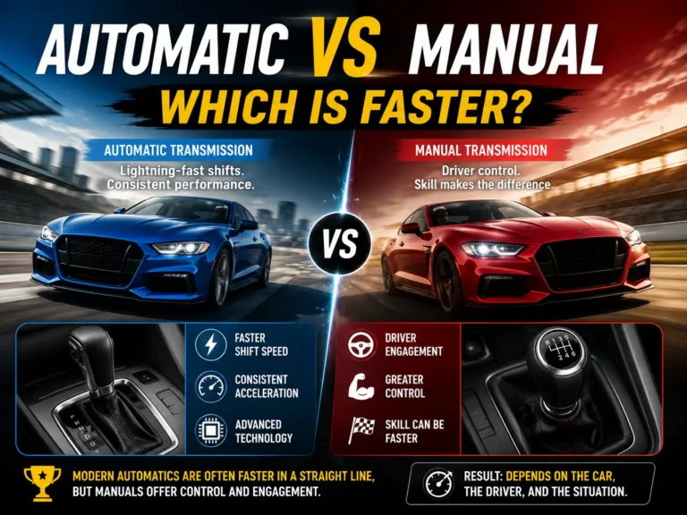
Manual vs Automatic: What’s Actually Different
Both a manual and an automatic gearbox do the same job: match engine speed and output torque to the driving conditions at any given moment. What differs is who controls the process — the driver, or the car’s electronics — and the hardware used to achieve it.
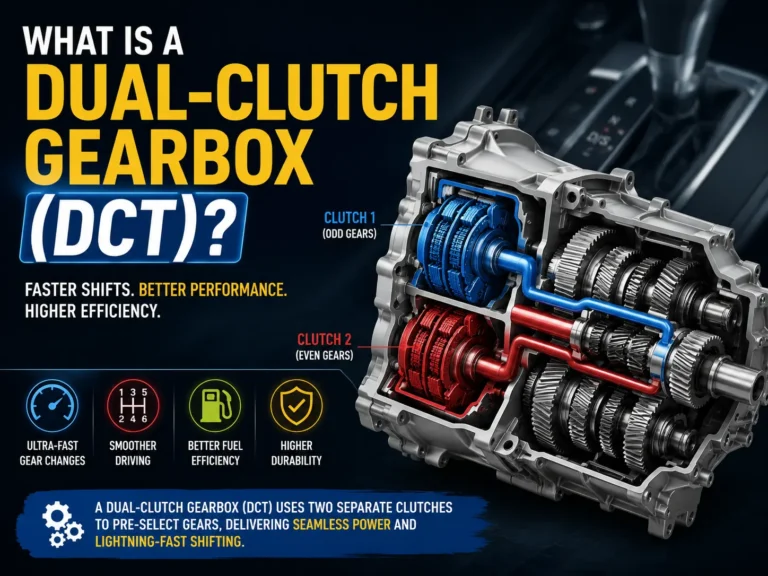
The “automatic is always slower” notion is outdated. A modern dual-clutch transmission — which is mechanically a pair of manual gearboxes operating in parallel, pre-selecting the next gear before the current one is released — can shift faster than any human hand on a stick shift. The aerodynamic and mechanical packaging of a modern Formula 1 car means sequential semi-automatics are the only viable option at that level.
For road driving, the manual’s advantages are simplicity, lower cost, driver control, and — for many enthusiasts — a more connected driving experience. On track, in a GT3 car or a IndyCar — the sequential or dual-clutch wins on pure speed every time.
Gear crunching: Most commonly worn or damaged synchromesh rings, or shifting too fast when cold. Difficult to engage gear: Could indicate clutch adjustment, a worn clutch plate, or worn selector forks. Jumping out of gear: Usually worn detent springs (the ball-and-spring that holds each gear position) or worn dog teeth. Whining noise: Often low gearbox oil or worn bearing. Check the gearbox oil level before assuming the worst — it’s the cheapest fix first.
Manual Gearbox FAQ
The Bottom Line on Manual Gearboxes
A manual gearbox is a carefully engineered system of parallel shafts, interchangeable gear pairs, and clever synchroniser technology — all working together to give an engine’s narrow powerband the flexibility to cover everything from a stationary start to motorway cruising. The clutch provides the break in power flow. The gear ratios provide the mechanical advantage. The synchromesh rings make it all usable without specialist skill.
What makes the manual gearbox remarkable isn’t any single component — it’s the elegance of how they work in sequence: the moment your foot presses the clutch pedal, a chain of mechanical events unfolds inside that housing in under a second, culminating in dog teeth locking home with a satisfying click. A hundred years of engineering refinement, contained in something small enough to hold in your lap.
For the full context on how all these drivetrain systems fit together in a racing environment, our Explained series and the World of Speed Archive are worth exploring further.